|
|
Construction Photographs
All photographs on this page © 2007, Larry Kerecman. Do not reproduce without permission.
Click photos for larger version.
Fountain Vault
Construction of the new Electric Fountain vault began in January after a delay
caused by the holiday snow storms. The foundation slab is 3 1/2 feet thick and the outer
walls, like the original, are battered with a taper from two feet thick at the base to one
foot thick at the top. The vault deck, which holds all of the water feature manifolds and
nozzles, is sixteen inches thick and the parapet wall, which hides all this plumbing from view,
is one foot thick.
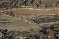
Aerial veiw showing the drained lake.
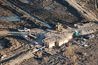
Aerial view of the fountain vault with the new 16" feed line installed.
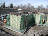
Epoxy-coated re-bar being installed for the battered walls of the new fountain vault.
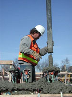
Pouring the concrete for the vault walls.
Fountain Deck
The new Electric Fountain duplicates the original 12 water
displays but will use modern plumbing
techniques to distribute the water to the nozzles. Both water pipes and electrical
conduits penetrate the roof of the new fountain vault to service the nozzles and lights on the
fountain deck. When the fountain is in operation, the vault deck is flooded to a depth of
30 inches behind a parapet wall.
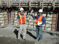
Colin Goodrich (Hobbs Architectural Fountains)
and Gary Coffey (Concrete Works of Colorado)
hold one of the 2" steel water pipes that will be embedded into the fountain vault roof.
Photo taken February 22, 2007
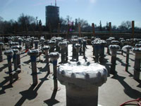
A view of some of the water and electrical
penetrations that go through the vault
ceiling to the deck above. Sixteen inches of concrete will be poured on this wooden form
after the re-bar is installed and the precision placement of these pipes is confirmed. The
manifolds holding the individual nozzles will attach to these pipes.
Photo taken February 22, 2007
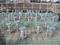
The lower course of re-bar and the re-bar for the support
beams has been installed in this picture.
Photo taken March 4, 2007
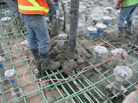
The concrete for the deck is being poured in these pictures.
A hose from a concrete pumping truck
allows the concrete to be fed from above so that it may be directed to flow in all areas of the deck.
Photo taken March 8, 2007
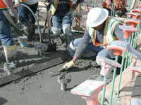
A vibrator is used to get the concrete to flow into the spaces
between the re-bar and
around the embedded water and electrical supply pipes.
Photo taken March 8, 2007
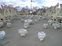
The concrete is all in place and awaiting final finishing
and leveling.
Photo taken March 8, 2007
Parapet Wall
The last concrete pour was for the parapet wall, which hides the fountain plumbing from
being seen from shore. When the fountain is in operation, a pool of water is formed behind
the wall to provide a stilling basin and cooling for the fountain lights. The water falling
back on the fountain deck spills over a weir on the east side of the fountain back into
the lake.
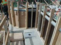
PVC pipe was cut in half to form the bullnose ornamentation around the
outside of the parapet wall.
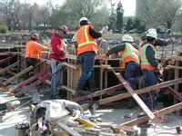
The multi-layer pier cap was formed as part of the parapet wall.
It provides the base for the ball finials.
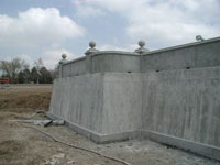
With the forms removed, all of the details of the
vault and parapet walls can be seen.
A thin horizontal line shows where the vault walls join the 16” thick deck. The rectangular
openings at the base of the parapet wall allow the fountain deck to drain back into the lake
when the fountain is shut off.
The twelve ball finials on the piers disappeared from the old fountain
some time in the 1930s. One of them was spotted in the mud when the lake was drained. The
new ones were made to match the originals. 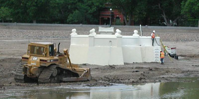
The entire fountain vault structure was coated with
a waterproofing membrane,
sprayed on at high pressure. The color turned from white to yellow with exposure to sunlight,
matching the shade of the original fountain paint. This photo was taken on May 18, 2007, just
before the water flowed back into Ferril Lake for the first time in 7 months.
|